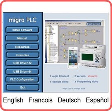
 When you click on links to various merchants on this site and make a purchase, this can result in this site earning a commission. Affiliate programs and affiliations include, but are not limited to, the eBay Partner Network. When you click on links to various merchants on this site and make a purchase, this can result in this site earning a commission. Affiliate programs and affiliations include, but are not limited to, the eBay Partner Network.
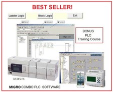
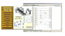
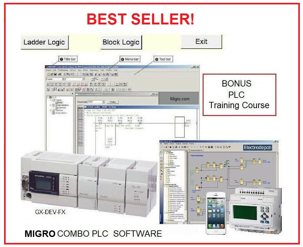
1 1 Migro Developer Ladder Logic
2 2 Block Function Logic Diagram
For upload and download your developed programs
For the following Hardware: PLC’s: Edplc, Easy, Rievtech, Xlogic, Migro, Mitsubishi FX series and more Featured: inputs,outputs and functions - Input Switchesoperable from the computer keyboard or by clicking on them.
- Instantaneous Relaycontacts (normally-open and normally-closed).
- Instantaneous Timercontacts (normally-open and normally-closed).
- Timed Timer and countercontacts
- Branch wiring
- Real Time Clock Day, Month, Years
- Compare Instructions (GRT, EQU, and LES).
- Analog inputs and scale simulator screen
- Latch and Unlatch Relays
- Master Control Relays (MCR)
- On-Delay Timers (TON)
- Off-Delay Timers (TOF)
- Retentive Timers (RTO)
- Counters
- Timer/Counter Reset (RES)
- Move (MOV)
- Math Outputs (ADD, SUB, MUL, and DIV)
- Logical Outputs (AND, OR, NOT, and XOR)
- And More
- Supports programming of complex logic functions
- Real time program monitor
- Impulse generator function and timers
- Display function for displaying and editing plain text messages and values
- Gain function for shifting analog signals
- Integrated Schmitt trigger controller
- Closed-loop controller applications
- Integrated calendar/clock function
- Up to 350 on/off switching commands per program
- Can replace a multi-channel real-time clock
- Large set of preprogrammed functions
- Process visualization and dynamic real time parameter graphics
- Program simulation – no controller needed
- Point, click, drag and drop programming
- Simple debugging
- Program up to 186 I/O
- Easy and convenient program creation and editing.
- Programs can be saved on a computer and accessed at any time.
- Programs can also be upload from the EDPLC controller and then edited.
- Enables users to print programs for reference and review.
- The Simulation Mode allows users to virtually run and test the program before it is loaded to the the EDPLC
- Real-time communication allows the user to monitor the EDPLC operation during RUN mode
Evaluation at every lesson
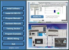
Table of ContentsLESSON 1 – Introduction and Overview1.1 Course Objectives 1.4 Course Product Line 2 – FX-Series Hardware Review2.1 What is a dedicated 52.2 FX Line of Hardware Components ................. 82.4 ....................... 102.5 Outputs Special Function High Speed Counter & Positioning 152.8 Communication Modules and Option Network Modules & Option Miscellaneous Power Exercise – Power Supply Calculation Memory Types 3 – Programming Equipment3.1 Hand-Held Programming Units Programming Software GX-Developer Overview File Format Hardware 4 – Number Systems4.1 Binary Numbers Hexadecimal Octal Binary Coded Decimal Exercise – Number 43LESSON 5 – Numeric Data in PLCs5.1 Integer (16/32 Decimal (16/23 6 – System Devices6. System 7 – Addressing7.1 Right Side Bus Rules of Addressing FX3U Left Side Bus Addressing Exercise – PLC Addressing 8 – Demo Kit Indicator Lights 9 – PLC Instruction Types9.1 Basic STL (Step Ladder) 599.3 Applied 10 – Basic Instructions10.1 Ladder Common Exercise – Ladder 65LESSON 11 – Develop and Edit Programs11.1 Creating a New 6811.3 Editing the Online Editing Monitor the Program 7211.7 Forcing Bits and Changing 7311.8 Exercise – Contacts and 73LESSON 12 – Timers and Counters Program Additional Timer Exercise – Timers 8212.6 Exercise – Conveyor Control 13 – Applied Instructions13.1 Data Transfer Comparison Instructions Exercise – Parking Lot Exercise – Conveyor Control 8813.6 Conversion 8813.7 Increment and Decrement Instructions Exercise – INC and 8913.9 Exercise – Binary Exercise – Parking Lot Part 2 Exercise – Conveyor Control Part High-Speed Processing TO/FROM Instructions Exercise – FX2N-5A Module Access Shift Registers Exercise – Bit Shift Register Program Flow Control 14 – Diagnostic Devices14.1 Special M Relays Special D Handy Troubleshooting Real Time Clock Usage Exercise – Daylight Savings 10014.6 GX-Developer Data 15 –
Software is FREE, cost include Procurement, Development,Production, examples and data compilation by Global Shipping Program only

|
|