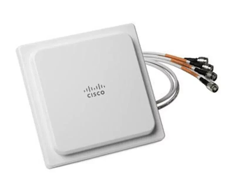
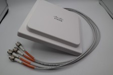
Cisco Aironet Four-Element, MIMO, Dual-Band Ceiling Mount Omni-Directional Antenna (AIR-ANT2524V4C-R= and AIR-ANT2524V4C-RS=)
Last Updated:February 06, 2020
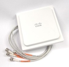
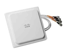
This document describes the AIR-ANT2524V4C-Rx= antennas, and provides specifications and mounting instructions. Both antennas are four-element, MIMO, dual-band antennas that operate in the 2.4 GHz and 5 GHz frequency ranges. Both antennas are designed for ceiling mounting in an indoor environment. The AIR-ANT2524V4C-RS= antenna includes self-identifying circuitry.
Technical Specifications
Antenna type
4-Element, Dual-band, Low Profile Omni
Operating frequency ranges
2400–2484 MHz
5150–5850 MHz
VSWR
2:1 or less in both bands
Peak gain
2.4-GHz band: 2 dBi
5-GHz band: 4 dBi
Polarization
Linear
Azimuth plane 3 dB beamwidth
Omni-directional
Elevation plane 3 dB beamwidth
2.4 GHz band: 69°
5 GHz band: 60°
Length
7.25 in (18.4 cm)
Width
7.25 in (18.4 cm)
Depth
1 in (2.5 cm)
Weight
1.3 lb (0.59 kg)
Cable
3 ft (91.4 cm) plenum rated, UV stable
Connector
RP-TNC
Environment
Indoor
Temperature range
32–133°F
(0–56°C)
2.4 GHz Element 1 Azimuth and Elevation Plane Patterns5 GHz Element 1 Azimuth and Elevation Plane Patterns
2.4 GHz Element 2 Azimuth and Elevation Plane Patterns5 GHz Element 2 Azimuth and Elevation Plane Patterns
2.4 GHz Element 3 Azimuth and Elevation Plane Patterns5 GHz Element 3 Azimuth and Elevation Plane Patterns
2.4 GHz Element 4 Azimuth and Elevation Plane Patterns5 GHz Element 4 Azimuth and Elevation Plane Patterns
System Requirements
This antenna is for indoor use with any Cisco Aironet radio device with dual-band (2.4 and 5 GHz) RP-TNC antenna ports. The antenna can be mounted on suspended ceiling tiles having a thickness between ½ in. (1.27 cm) and 1 in. (2.54 cm).
The Self Identifying Antenna model AIR-ANT2524V4C-RS= is supported only on Cisco Catalyst 9800 Series Wireless Controllers running an IOS-XE 17.4.1 release or a later release. This antenna model is not supported on Cisco AireOS Wireless Controllers.
Safety Instructions
Follow these safety instructions when installing your antenna.
■Plan your installation procedure carefully and completely before you begin.
■If you are installing an antenna for the first time, for your own safety as well as others, seek professional assistance. Consult your dealer, who can explain which mounting method to use for the location where you intend to install the antenna.
■Select your installation site with safety, as well as performance, in mind. Remember that electric power cables and telephone lines look alike. For your safety, assume that any line is an electric power line until determined otherwise.
■Call your local power company or building maintenance organization if you are unsure about cables close to your mounting location.
■When installing your antenna:
–Do notuse a metal ladder.
–Dress properly: shoes with rubber soles and heels, rubber gloves, and a long sleeved shirt or jacket.
■If an accident or emergency occurs with the power lines, call for qualified emergency help immediately.
Installation Notes
Because antennas transmit and receive radio signals, they are susceptible to RF obstructions and common sources of interference that can reduce throughput and range of the device to which they are connected. Follow these guidelines to ensure the best possible performance:
■Mount the antenna to utilize its propagation characteristics. A way to do this is to orient the antenna horizontally as high as possible at or near the center of its coverage area.
■Keep the antenna away from metal obstructions such as heating and air-conditioning ducts, large ceiling trusses, building superstructures, and major power cabling runs. If necessary, use a rigid conduit to lower the antenna away from these obstructions.
■The density of the materials used in a building’s construction determines the number of walls the signal must pass through and still maintain adequate coverage. Consider the following before choosing the location to install your antenna:
–Paper and vinyl walls have very little affect on signal penetration.
–Solid and pre-cast concrete walls limit signal penetration to one or two walls without degrading coverage.
–Concrete and wood block walls limit signal penetration to three or four walls.
–A signal can penetrate five or six walls constructed of drywall or wood.
–A thick metal wall causes signals to reflect off, causing poor penetration.
–A wire mesh spaced between 1 and 1 1/2 in. (2.54 and 3.81 cm) acts as a harmonic reflector that blocks a 2.4 GHz radio signal.
■Install the antenna away from microwave ovens and 2-GHz cordless phones. These products can cause signal interference because they operate in the same frequency range as the device to which your antenna is connected.
■Install the antenna horizontally to maximize signal propagation.
Choosing a Mounting Location
Mount the antenna mounted clear of obstructions to the sides of the radiating elements. Generally, the higher an antenna is above the floor, the better it performs. If possible, mount the antenna on the ceiling panel within 12 in. (30.5 cm) of the access point so you can connect its cables directly to the access point. If you must mount the antenna farther away from the access point, try to make the distance as short as possible.
Installing the Antenna
You can install the antenna on a ceiling tile having a thickness between ½ in. (1.27 cm) and 1 in. (2.54 cm).
Package Contents
Each antenna package contains the following items:
■AIR-ANT2524V4C-R= or AIR-ANT2524V4C-RS= antenna
■1” Nut
Tools and Equipment Required
The following tools and equipment are not provided:
■1" (2.54 cm) hole saw to create a hole in the suspended ceiling tile
■A step ladder high enough to access your ceiling safely
Installing the Antenna
The antenna is installed to a suspended ceiling tile with a supplied 1 in. (2.54 cm) plastic nut. SeeFigure 1for details.
The antenna cables terminate with a straight RP-TNC plug connector after a 36 in. (91.44 cm) cable. The mating connector to the antenna on the access point is an RP-TNC jack.
Mounting the Antenna on a Ceiling Tile
Figure 1Ceiling Tile Mounting Details
To mount the antenna on a suspended ceiling tile:
1.Mark the mounting location on the ceiling tile.
2.Remove the ceiling tile from the ceiling grids.
3.Use a 1" (2.54 cm) hole saw to cut a hole in the ceiling tile.
4.Insert the antenna cables, one at a time, through the hole in the ceiling tile.
5.Insert the antenna cables, one at a time, through the hole in the plastic nut as shown inFigure 1.
Note:Do not use the rubber gasket when you mount the antenna on a ceiling tile. The gasket is not required for ceiling tile installations.
6.Ensure that the antenna is properly positioned on the ceiling tile and then tighten the plastic nut hand-tight.
7.Reinstall the ceiling tile.
8.Connect the antenna cables to the access point.
Note:The 5 GHz antenna cables are identified by a orange collar near the connectors. Ensure that you connect these cables to the 5 GHz antenna connection on the access point.
Connecting the Antenna to the Access Point
The AIR-ANT2524V4C-R= has four cables with orange labels. The four cables can be connected to any of the four ports on the access point.
The AIR-ANT2524V4C-RS= includes circuitry to enable self-identification of the antenna by the Cisco Catalyst 91xx Series access points. The antenna has three cables with orange labels and one cable with a purple label. The self identifying function is indicated by the purple label on this cable. Ensure that this antenna cable is connected to Port A on the AP, which is also designated by purple text around the RP-TNC connector. The AIR-ANT2524V4C-RS= antenna has a built-in EEPROM that can be read by the AP to automatically configure the antenna type and gain in the wireless controller.
Suggested Cable
We recommend using a high-quality, low-loss cable with the antenna.
Note:Coaxial cable loses efficiency as the frequency increases, resulting in signal loss. Keep the cable as short as possible as cable length determines the amount of signal loss (the longer the run, the greater the loss).